Simple Box
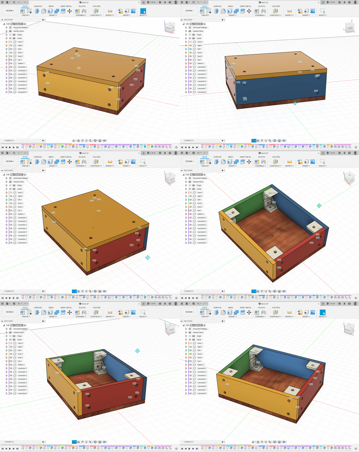
- The finished model is a simple box made from
3 mmplastic sheet. - Use separate components for the six panels.
- 3D-printed corner connectors hold the box together without glue.
1. Define the Internal Dimensions
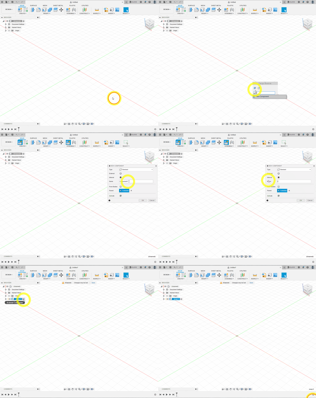
Press S, search for New Component and create a component named inner. It represents the free space inside the box; changing its parameters will resize the whole design.
💡TIP
After creating a component, make sure the activation dot appears beside inner in the Browser.
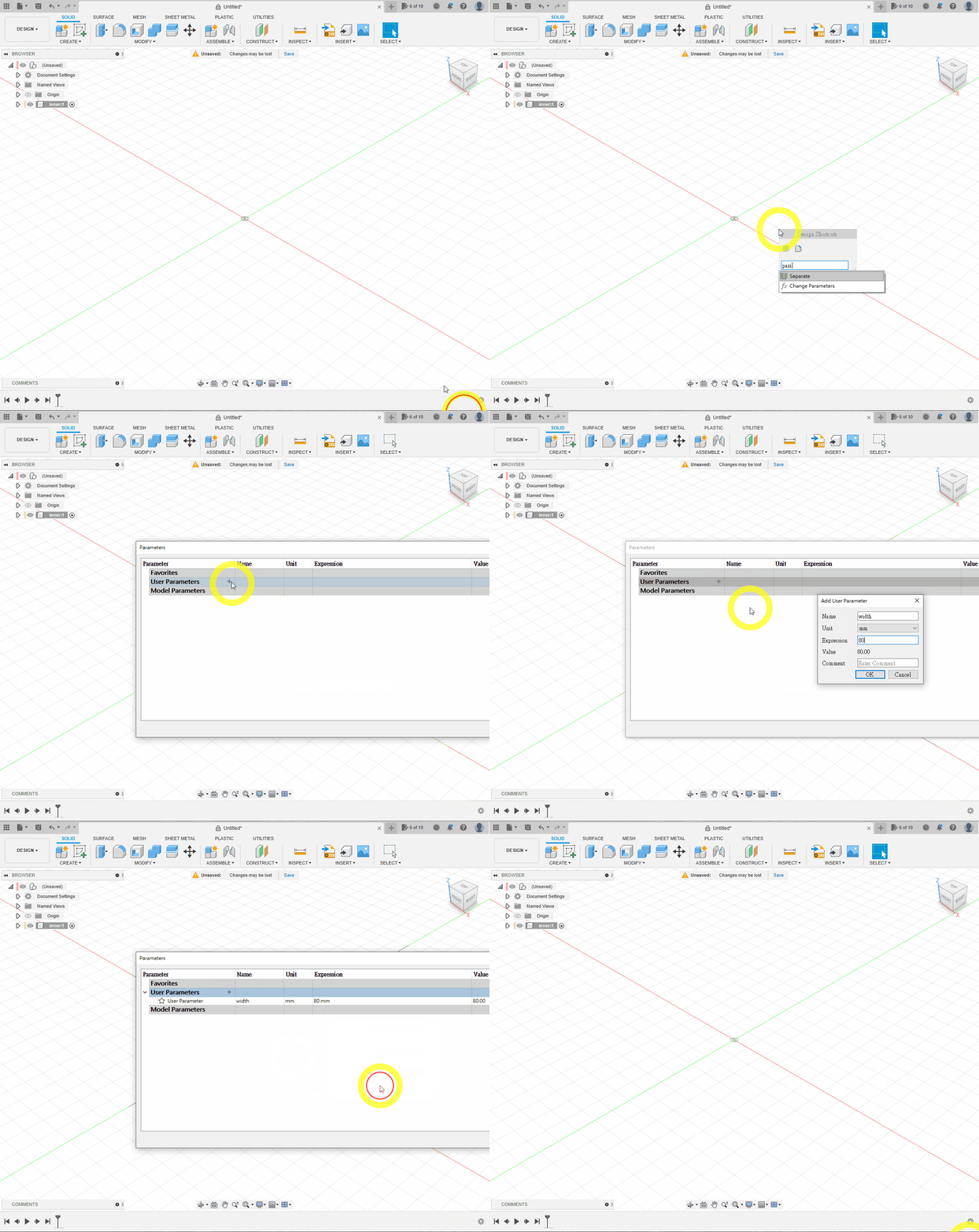
Press S, search for Parameter, and open Change Parameters. Create a parameter named width, leave the unit as millimetres and set its expression to 80.
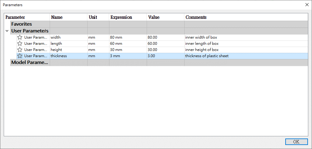
Create the other parameters shown: the box length, width, height and sheet thickness.
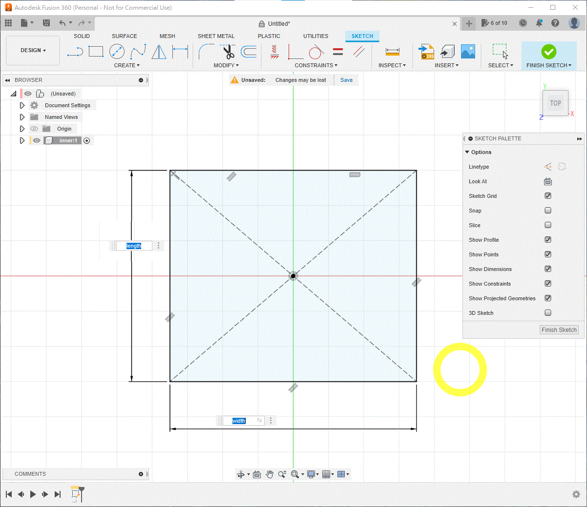
Click OK, create a sketch on the XY plane and draw a centre rectangle at the origin. Enter width and length as its dimensions; using the parameter names makes the sketch update automatically.
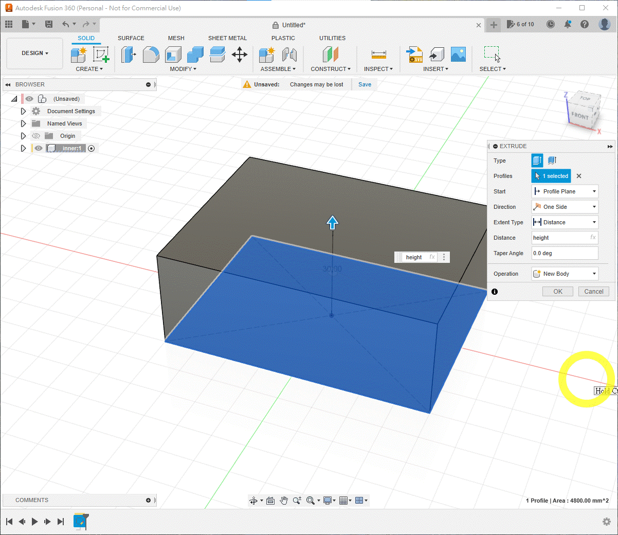
Extrude the rectangle by height.
2. Create the Six Outer Panels
💡TIP
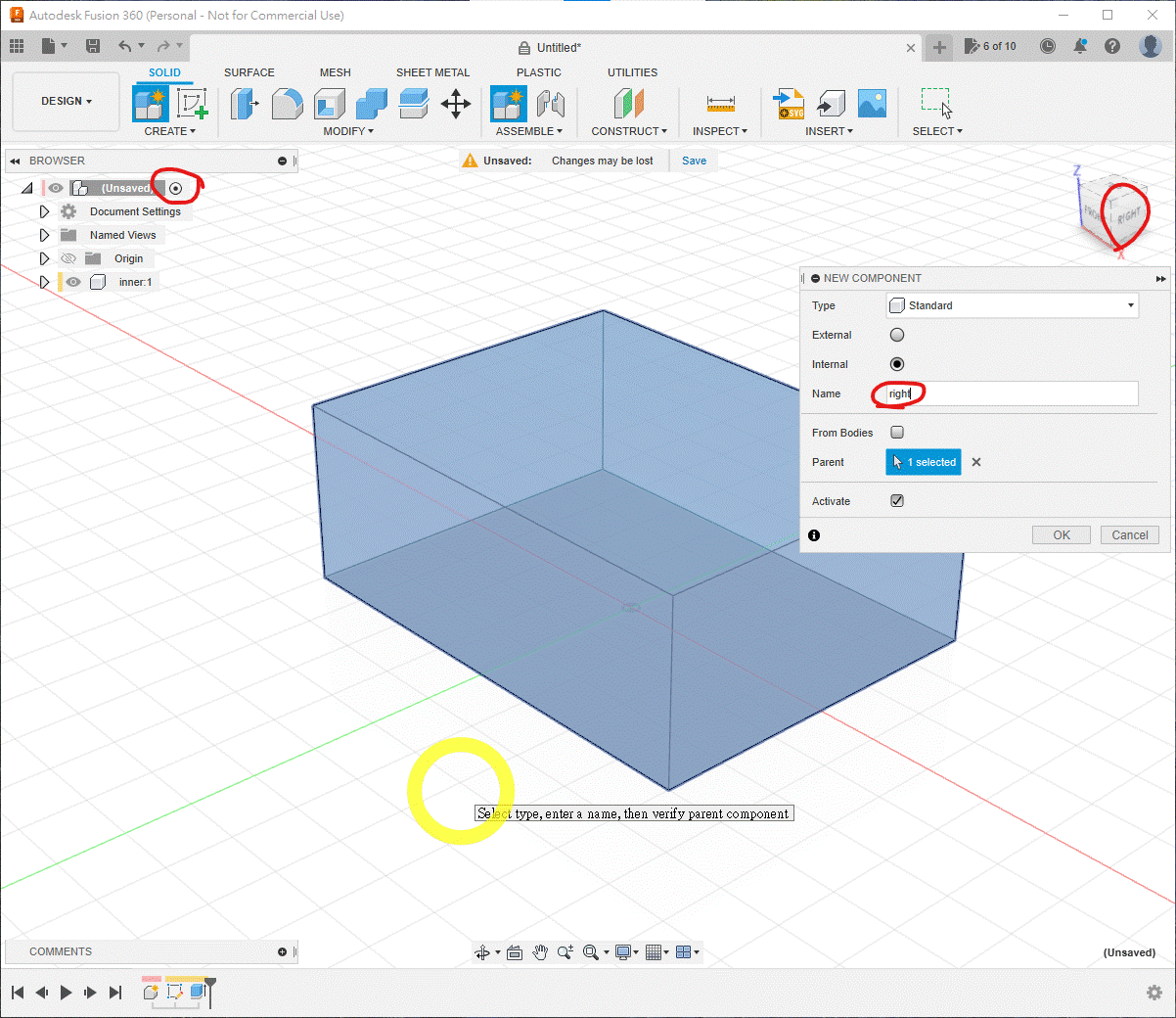
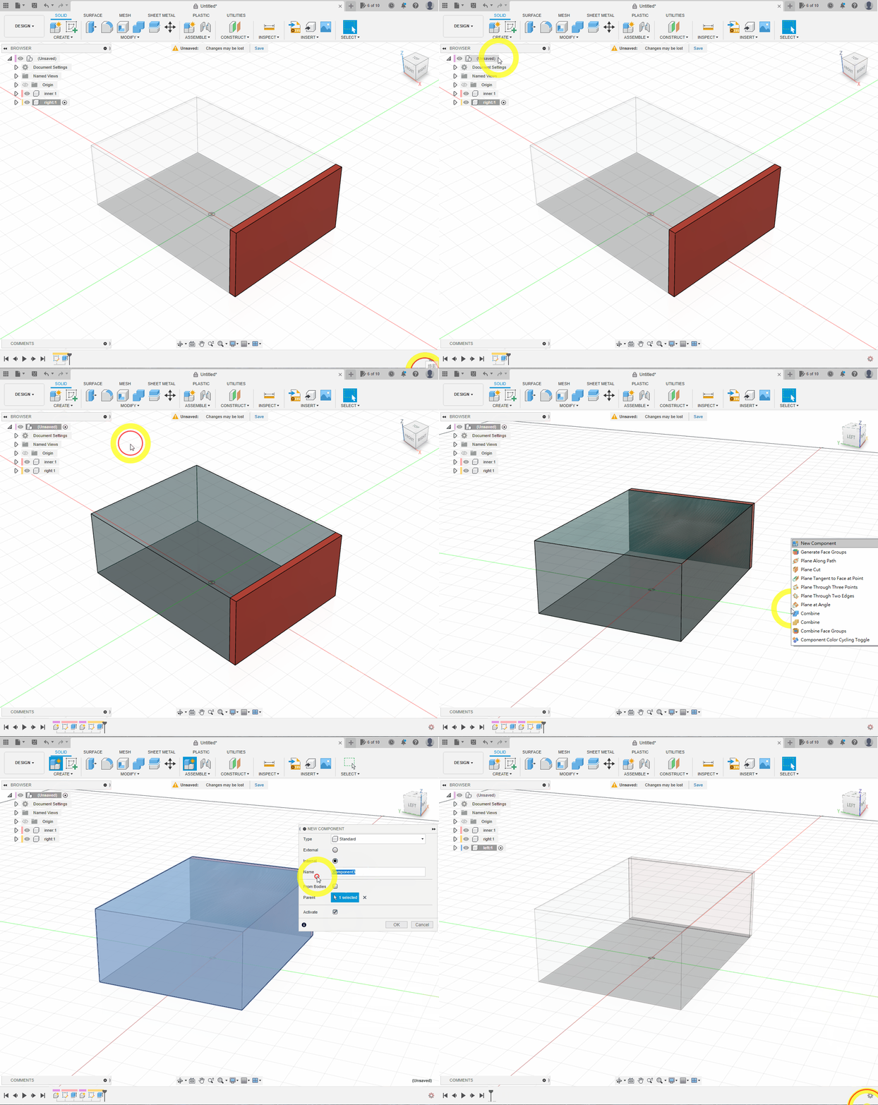
Reactivate the top-level assembly before creating each new panel component, then activate the new component before editing it.
Create a component named right.
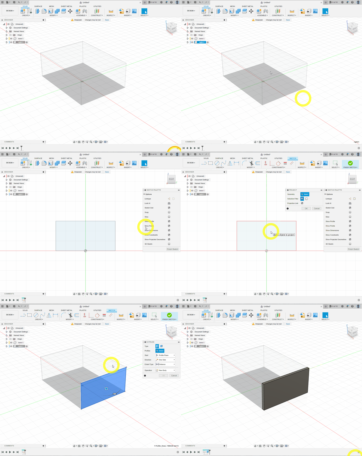
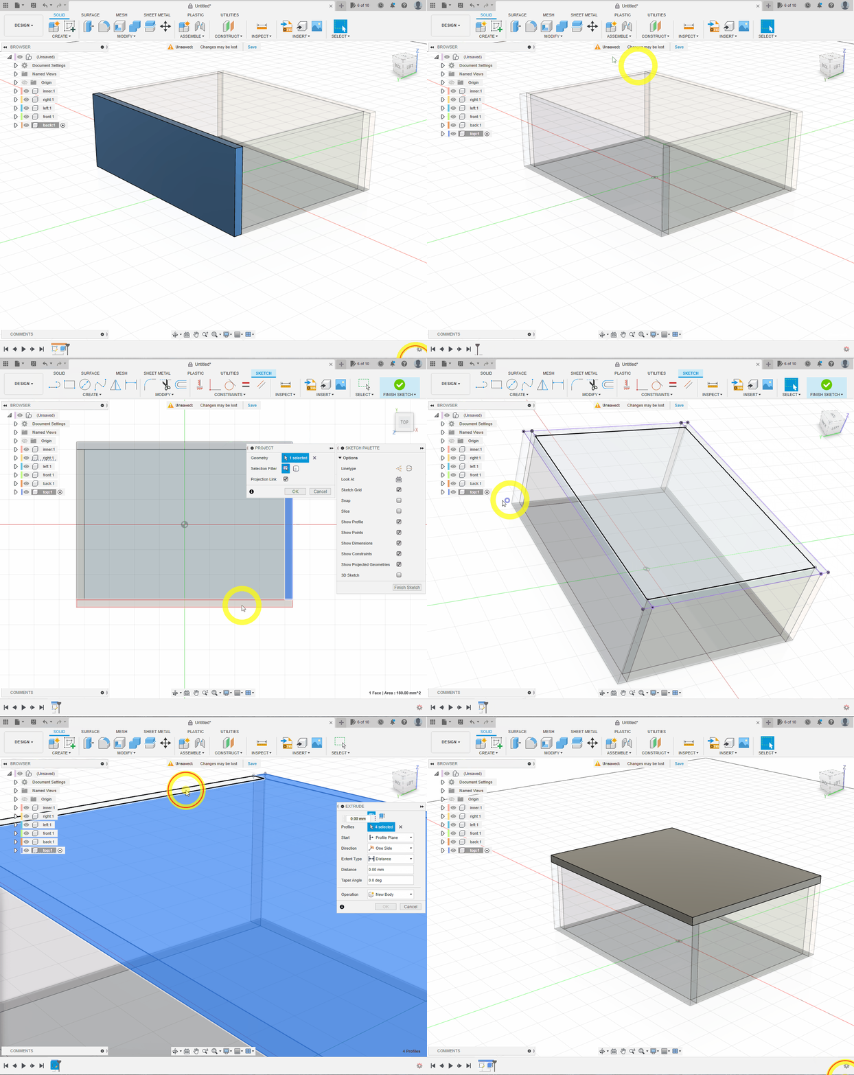
Create a sketch, press P to project the right side of inner, then press E and extrude it by thickness.
Repeat the process for a component named left: project the left side of inner and extrude by thickness.
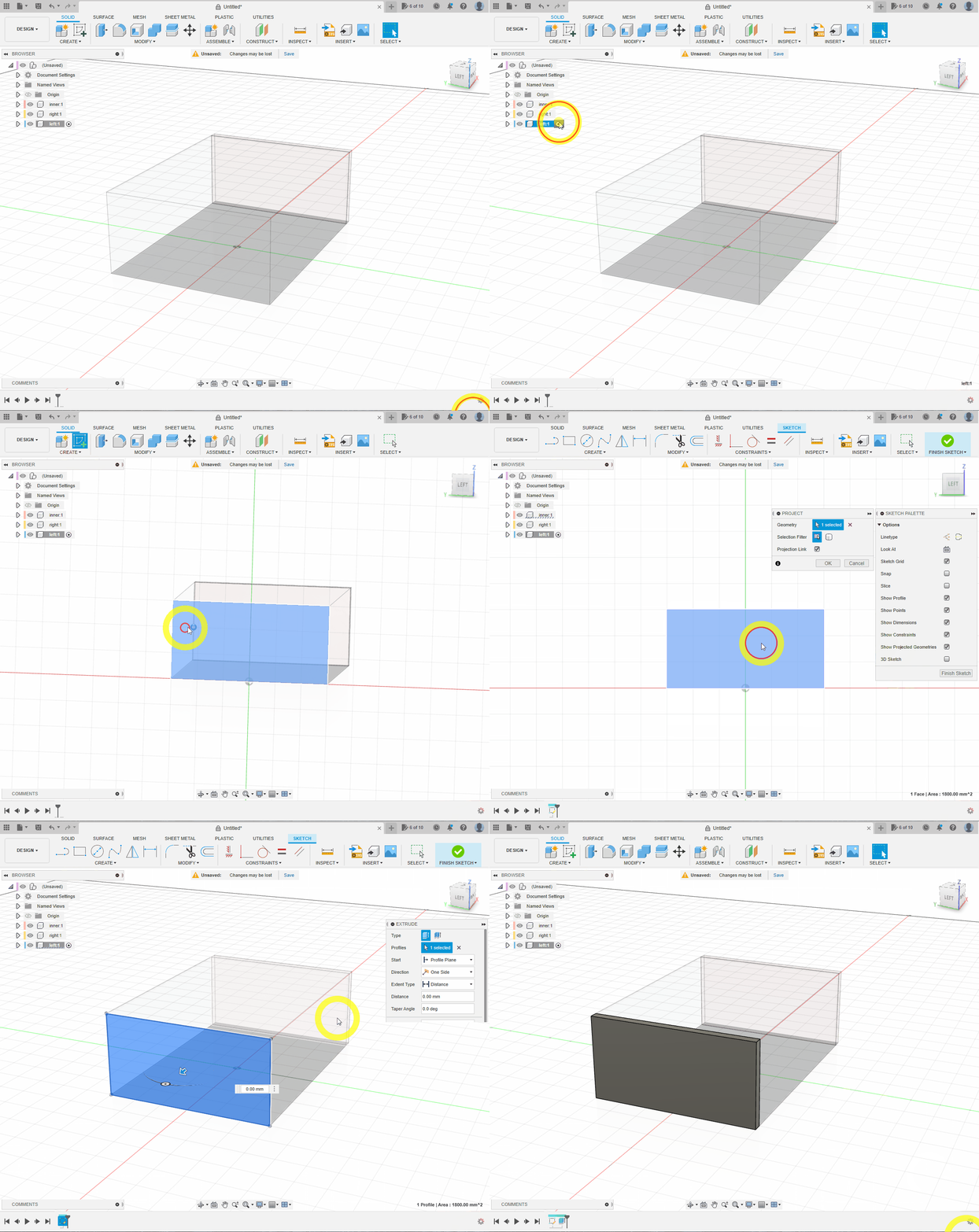
Create front. Project the front of inner together with the side faces of the left and right panels, then extrude by thickness.
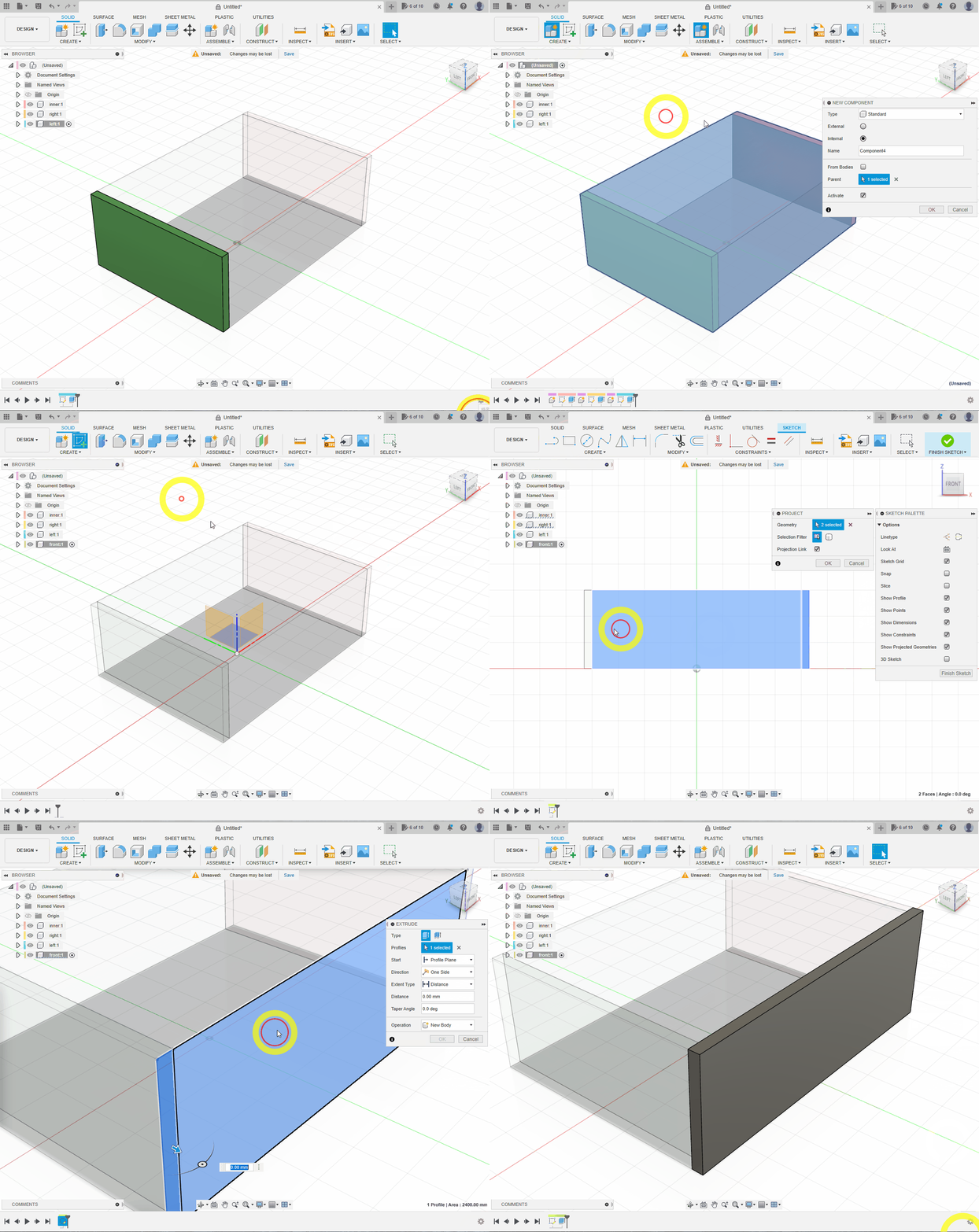
Create back in the same way on the rear face, including both side panels in the projection.
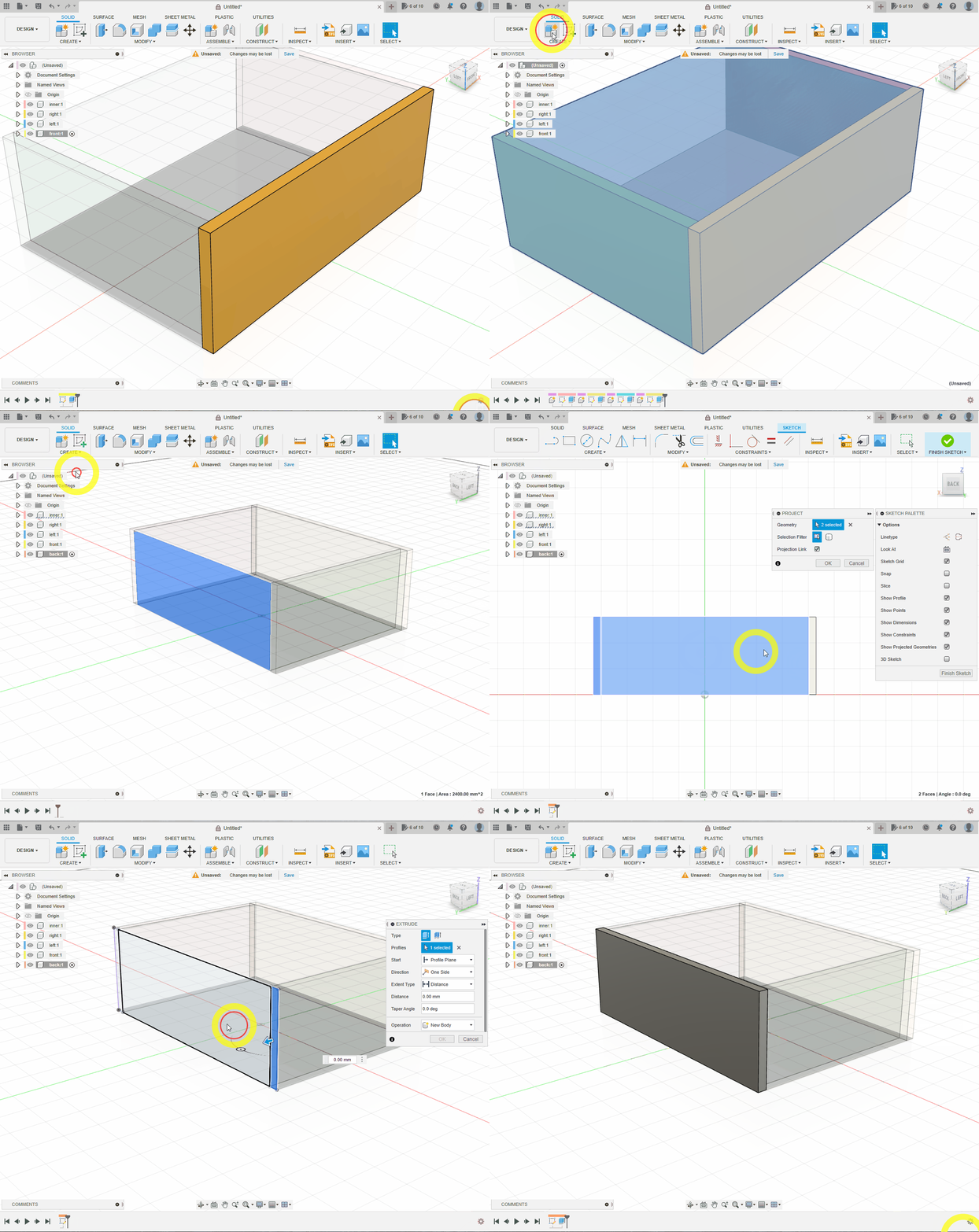
Create top. Project the top outlines of the front, back, left and right panels, then extrude by thickness.
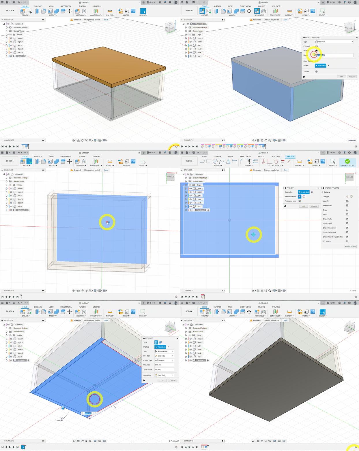
Create bottom at the bottom of the box in the same way.
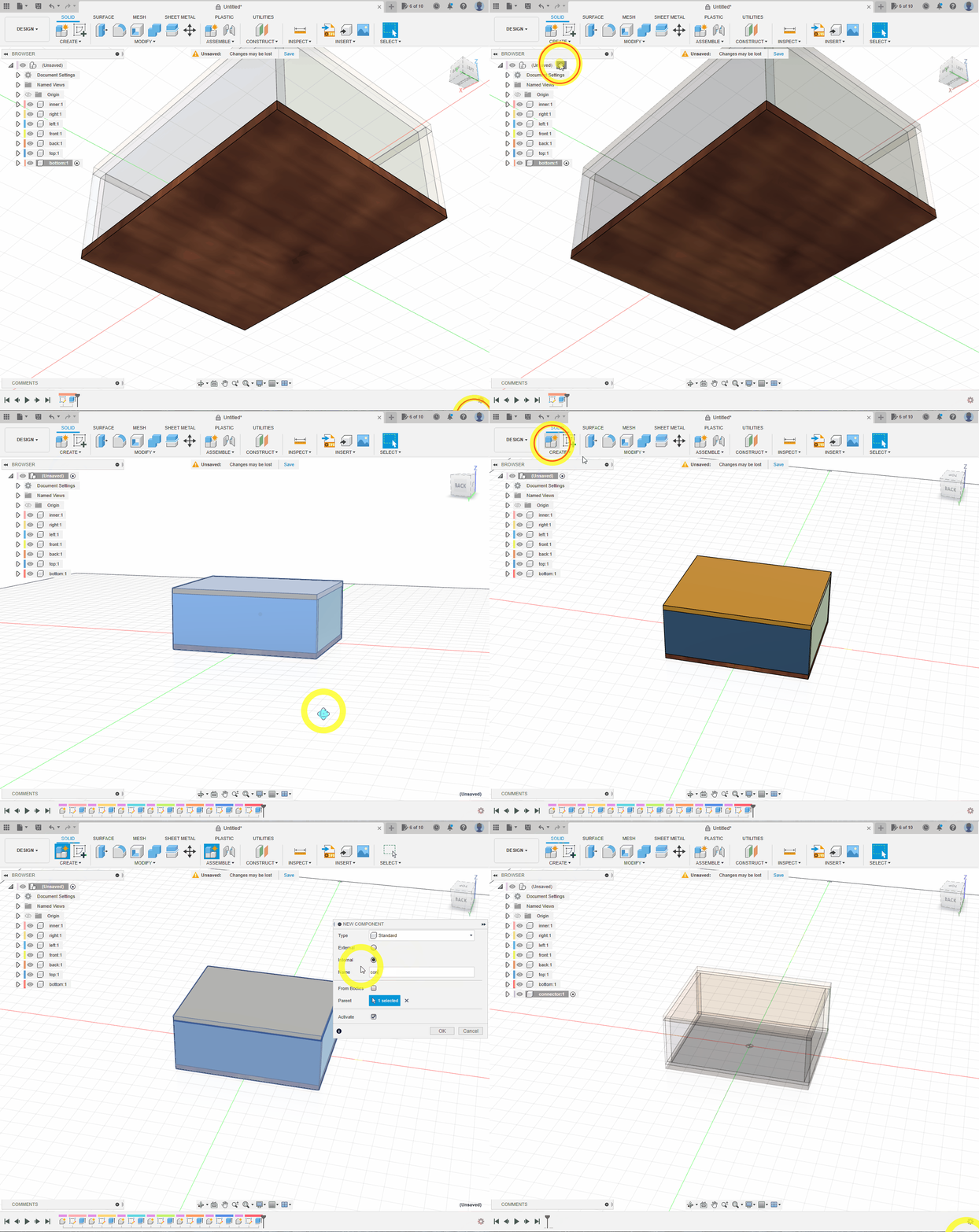
3. Model the 3D-Printed Connector
Reactivate the top level and create a component named connector.
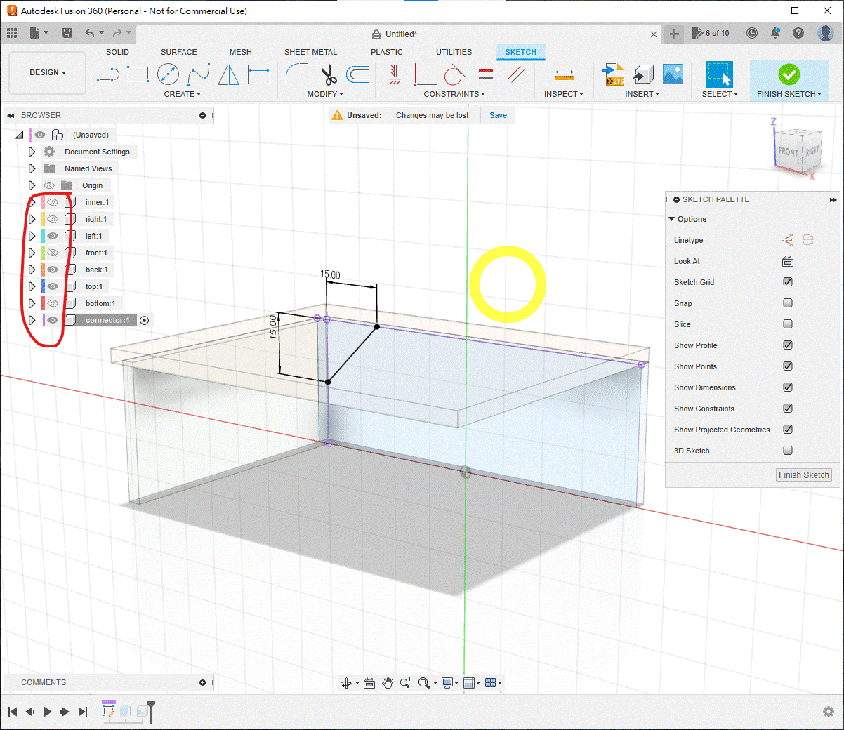
Hide inner and enough panels to leave only the three faces around one inside corner. Create a sketch there, project the inner edges with P, and draw a 15 × 15 mm right triangle.
Extrude it by 15 mm.
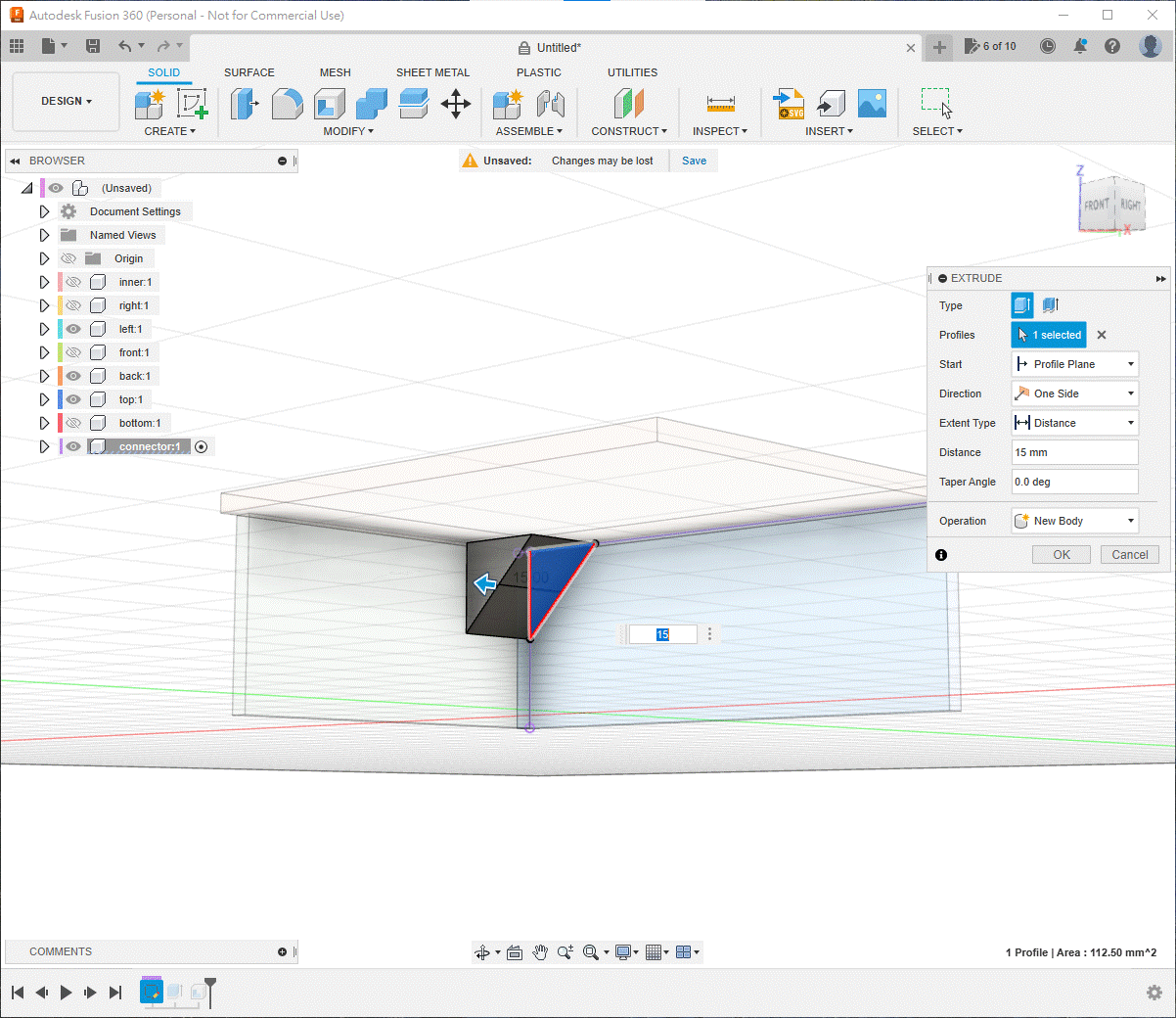
Use Shell, select the two faces shown and create a 2.5 mm inside shell.
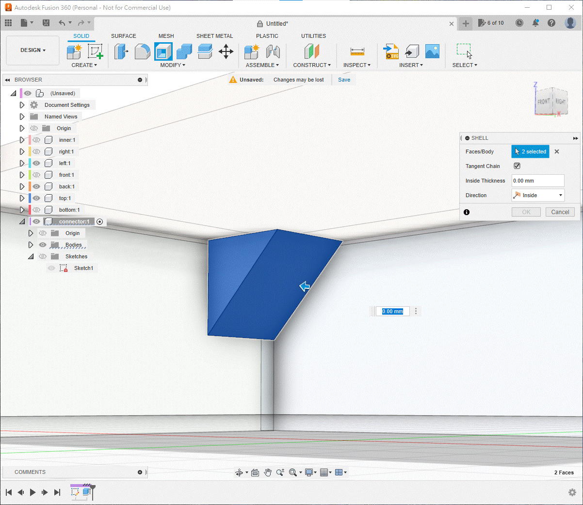
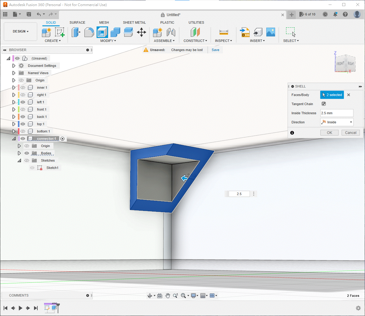
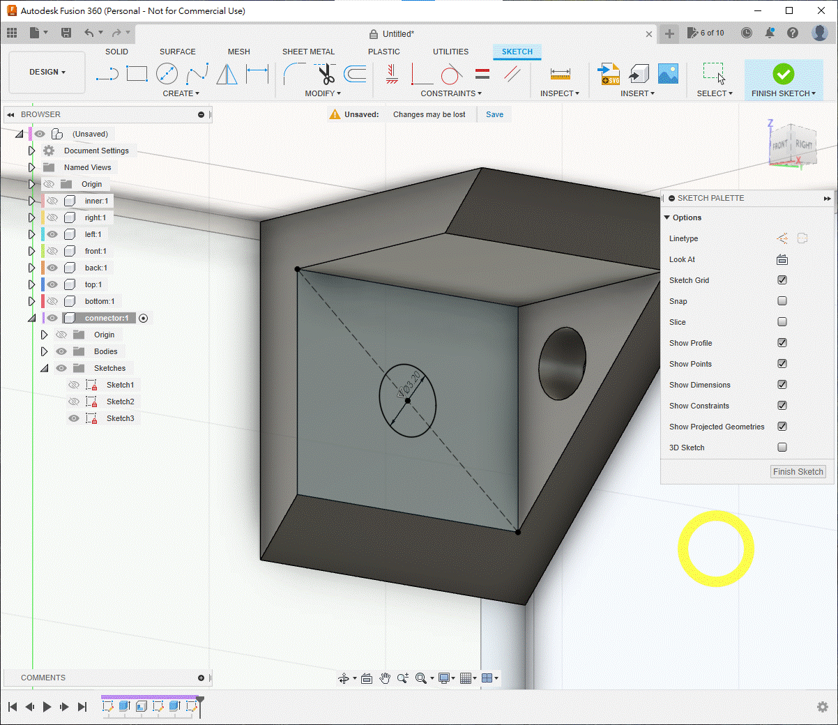
Add the screw holes. Use 3.2 mm for an M3 machine screw and nut, or about 2.9 mm for an M3 self-tapping screw. If undecided, create a screwSize parameter and use it for every hole.
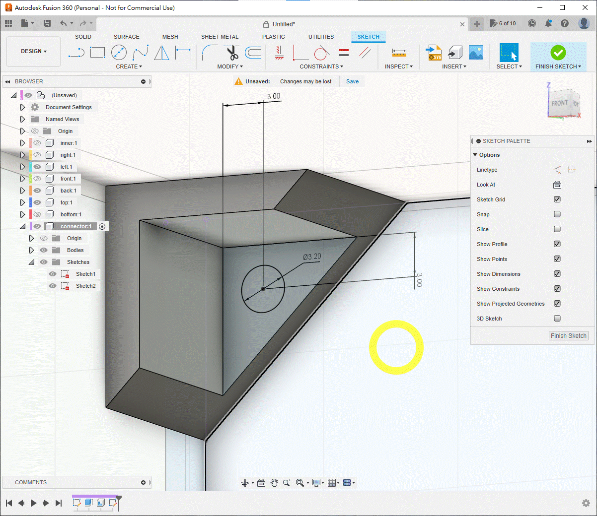
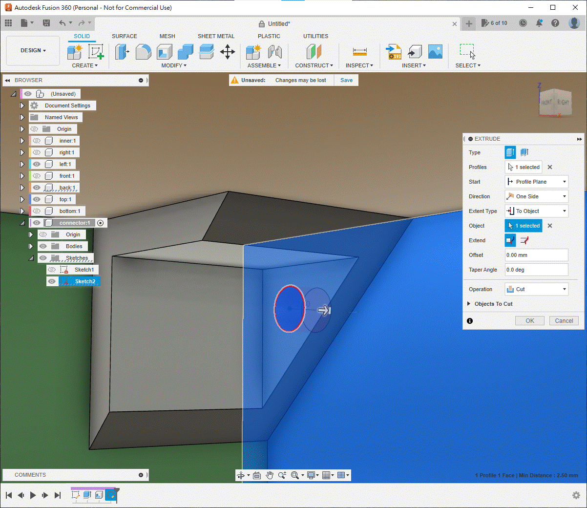
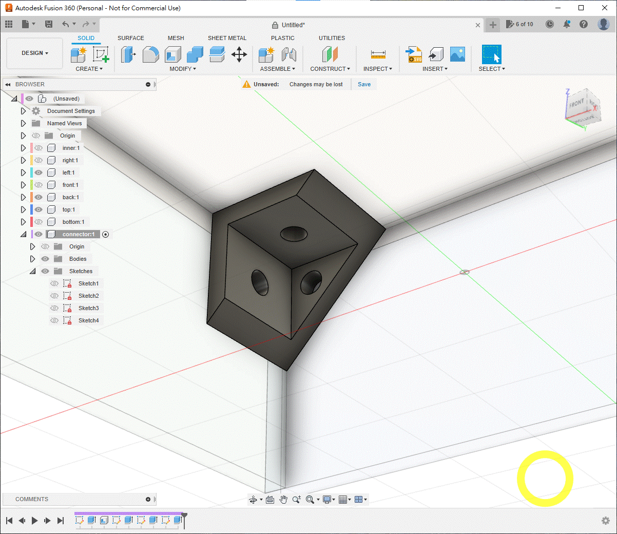
Add holes to the left and top faces: draw a diagonal construction line, place a 3.2 mm circle at its midpoint and cut with E.
4. Add Mounting Holes to the Panels
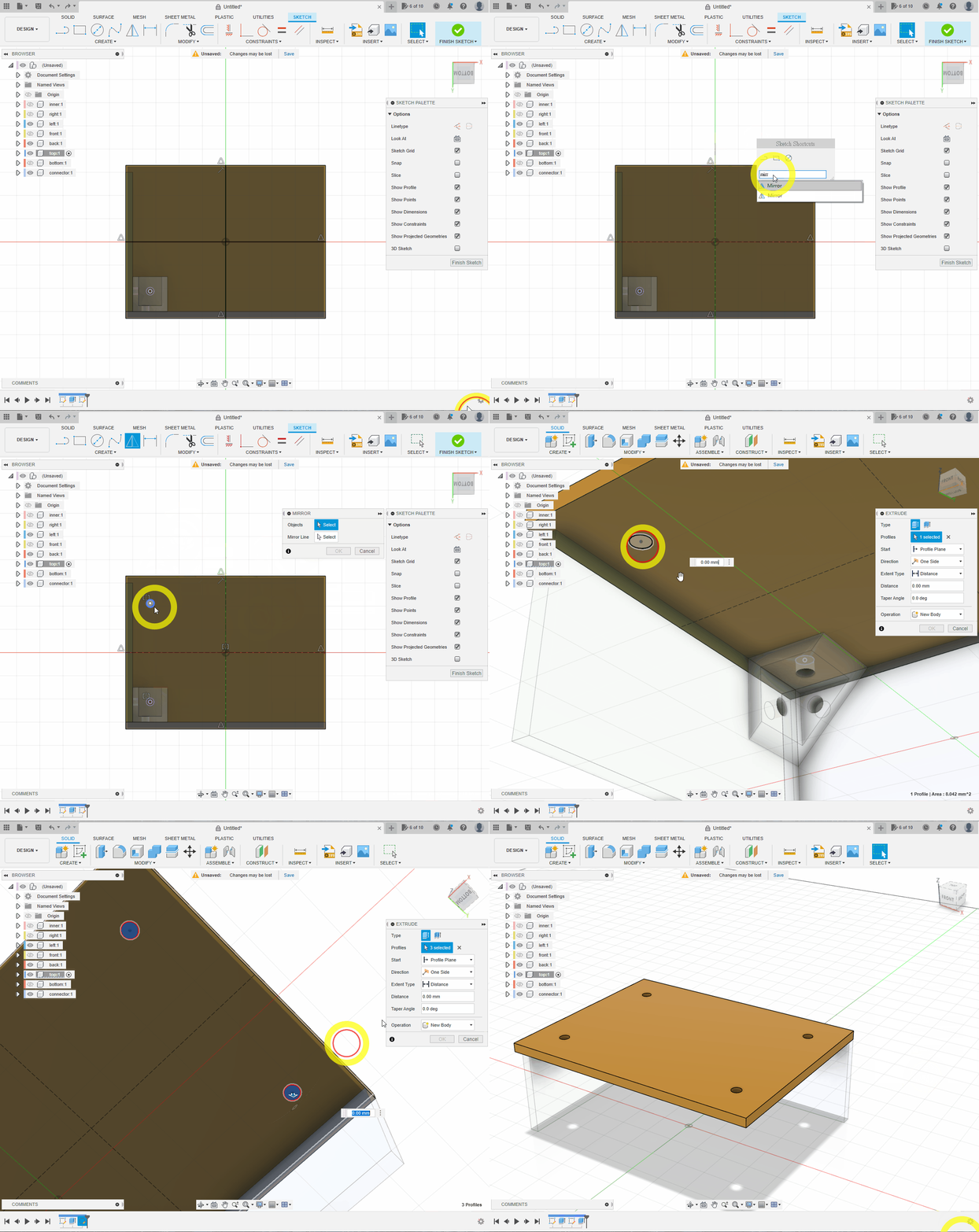
Activate top, create a sketch underneath it and press P to project the connector hole. Draw two centrelines and use Mirror twice to copy the circle to all four corners. Press E and cut the four holes.
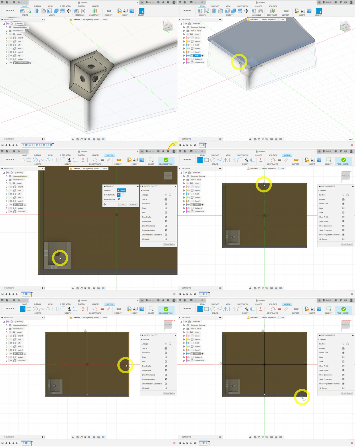
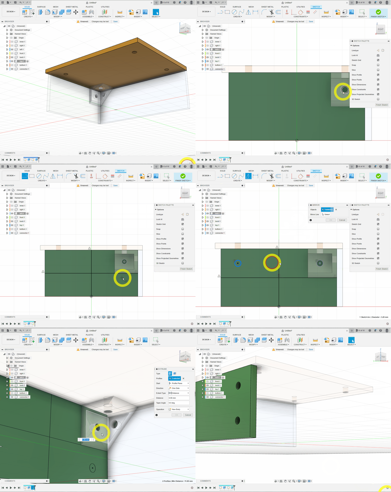
Repeat the projection, two mirrors and cut for the left and back components.
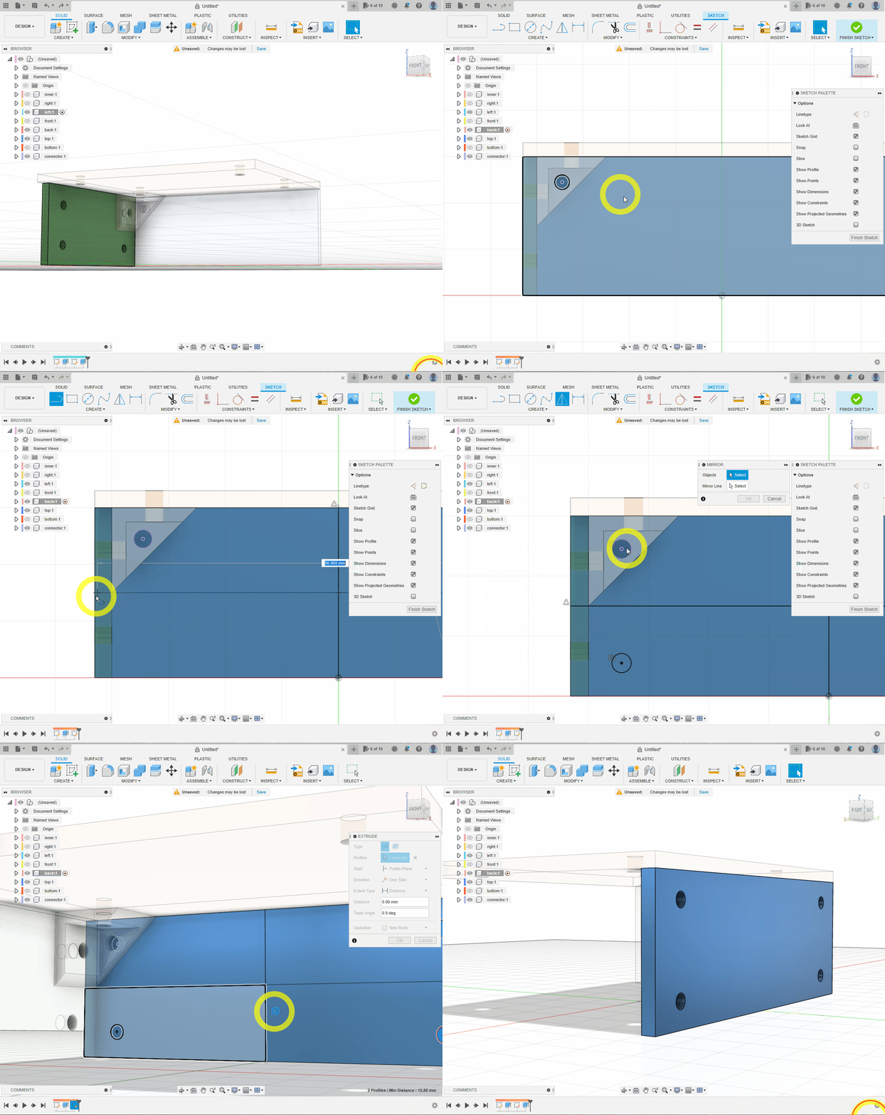
Reactivate the top level and show all six panels.
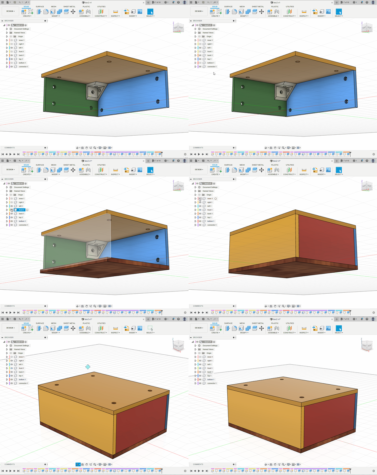
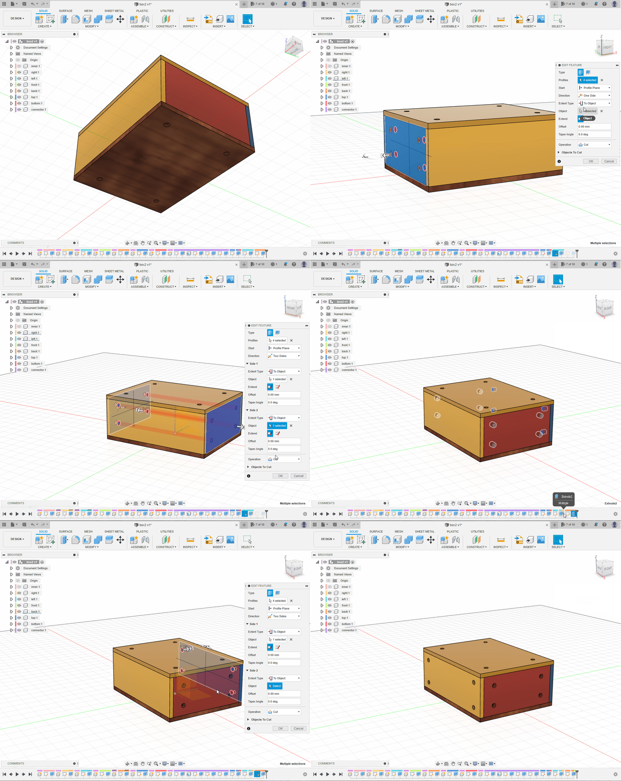
Reuse the top-panel cut for the bottom: find the original Extrude feature in the timeline, edit it from One Side to Two Sides, extend it through the bottom panel and add that body under Objects to Cut.
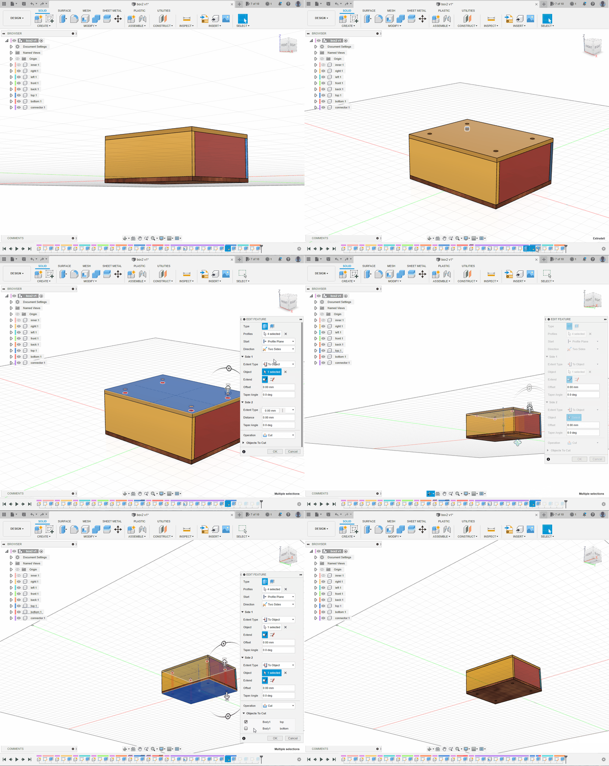
Do the same with the left and back cuts to create matching holes in the right and front panels.
5. Assemble the Box
💡TIP
- Press
Jor search forJoint. - Joints work between components, not bodies.
- Hold
Ctrlwhile selecting a circular edge to lock the intended face.
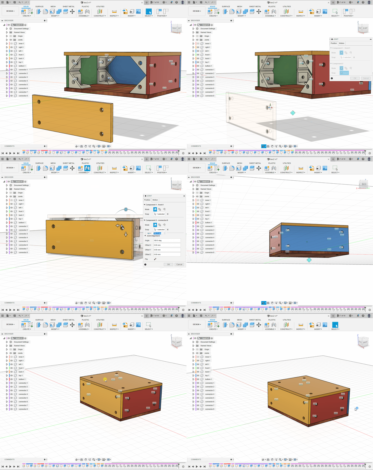
Move the six panels apart slightly. Press J, select the outside of a connector hole and then the matching panel hole.
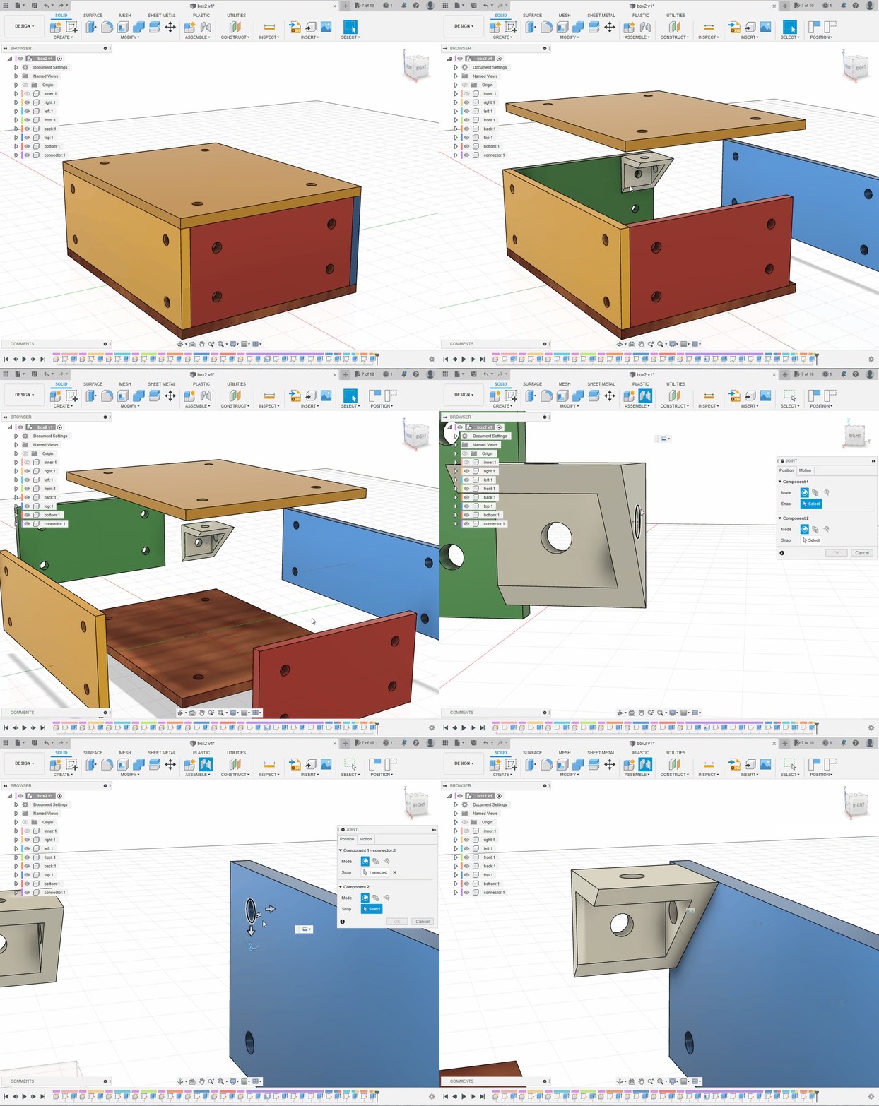
Joint the other two panels to the connector. The connector is not symmetrical, so match each of its three faces correctly. Drag the assembly gently to confirm that all three panels move together.
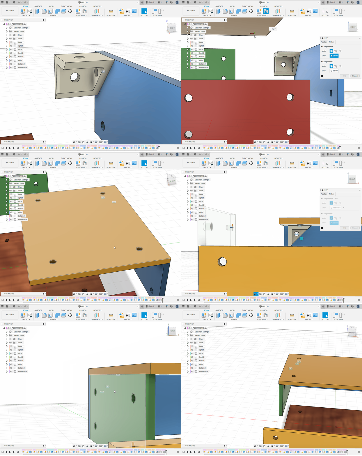
At the top level, select connector:1, copy and paste it in place, then move the copy aside. Repeat until there are four connectors.
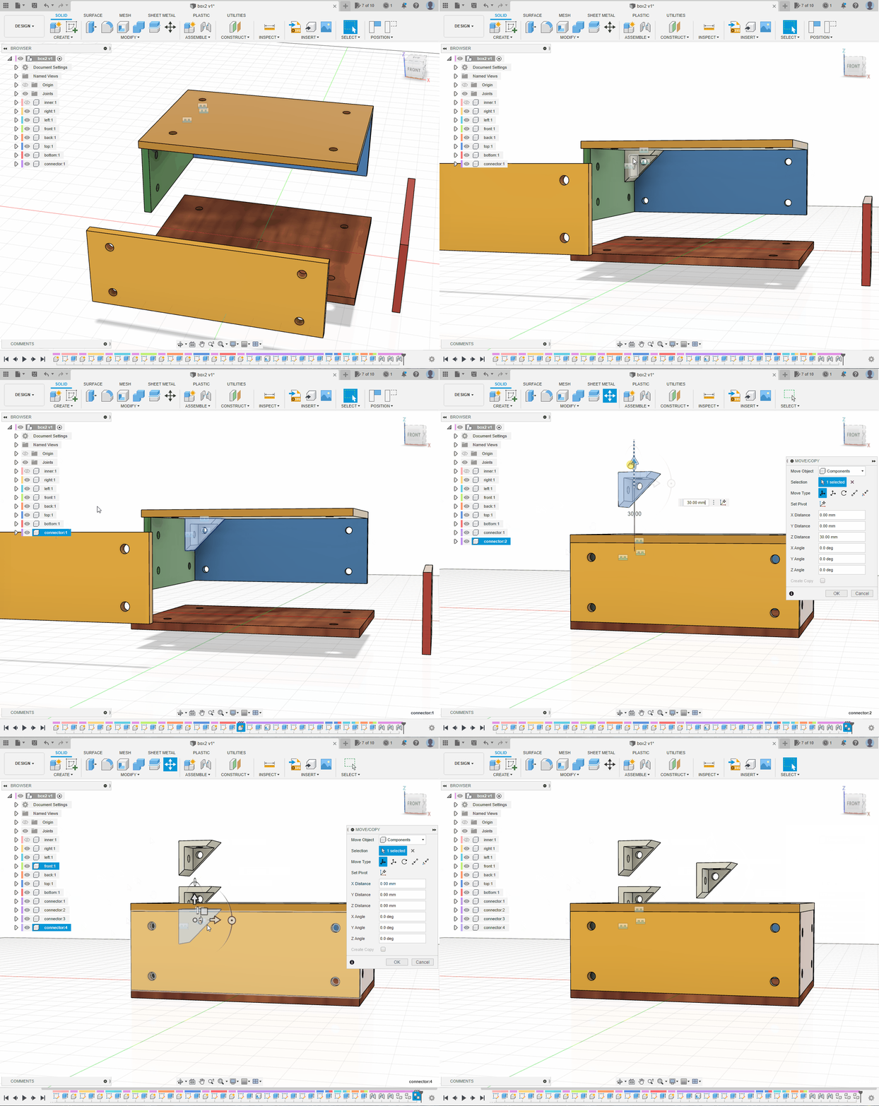
Use J to attach all four connectors to the back panel. Rotate a connector after selecting the two joint points if necessary.
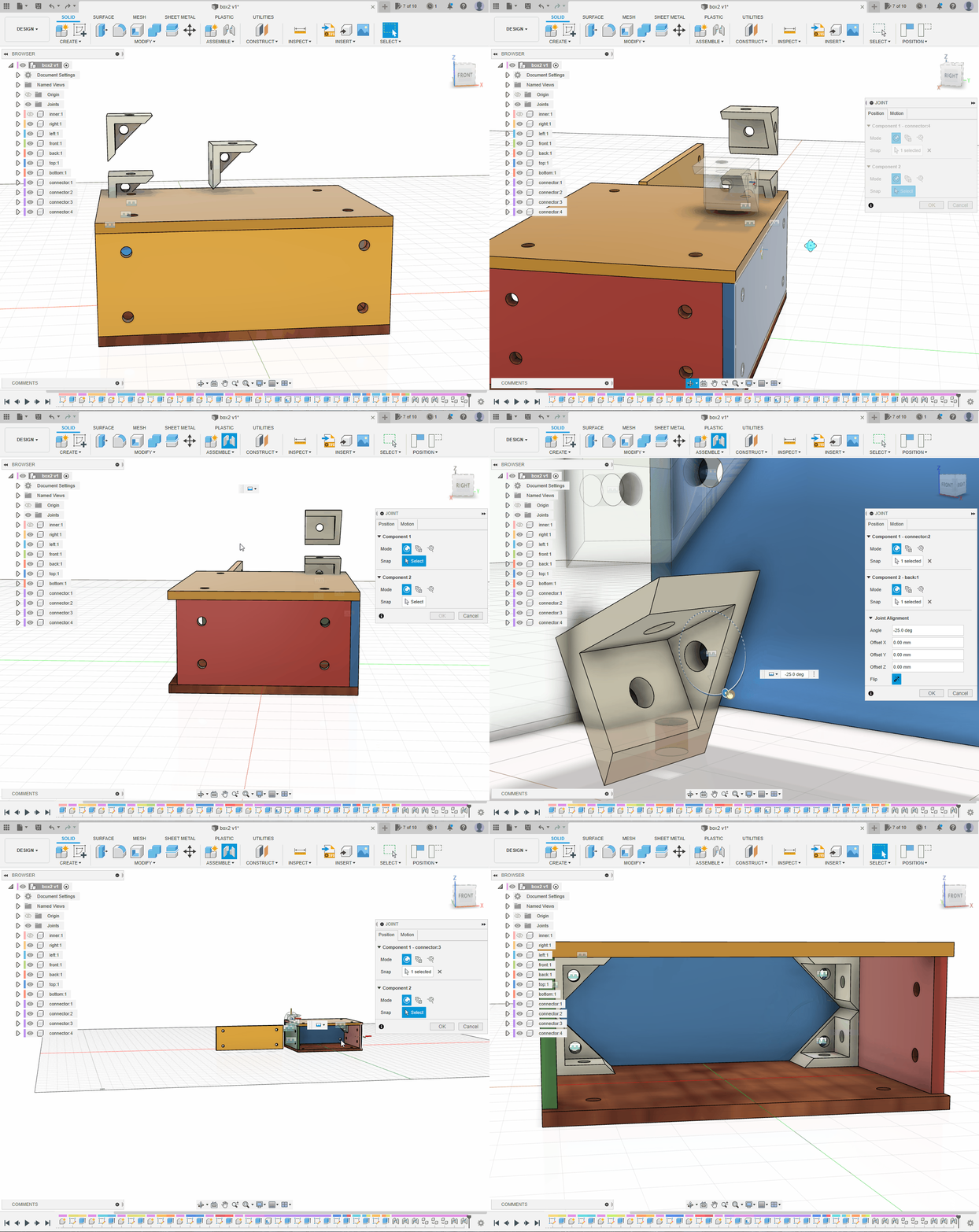
Move unassembled panels aside and joint the remaining panels.
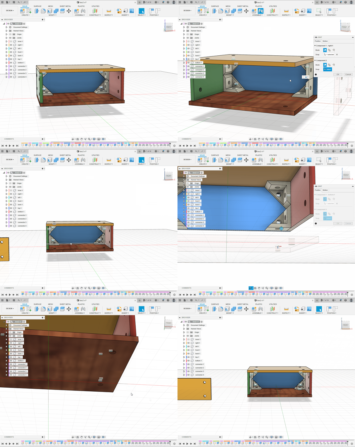
Hold Shift and select connector:1 through connector:4, then copy and paste the group. Move and rotate the copies into a convenient position.
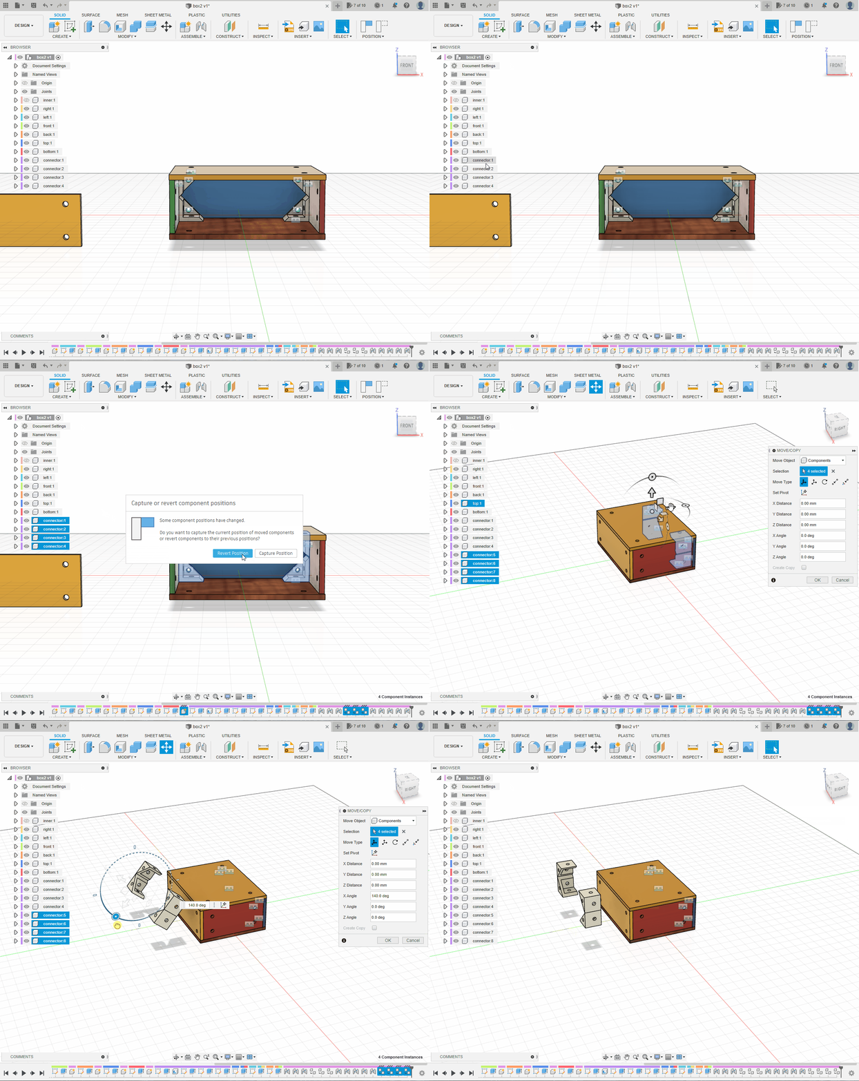
Create four more joints to attach the copied connectors to the top or side panels.
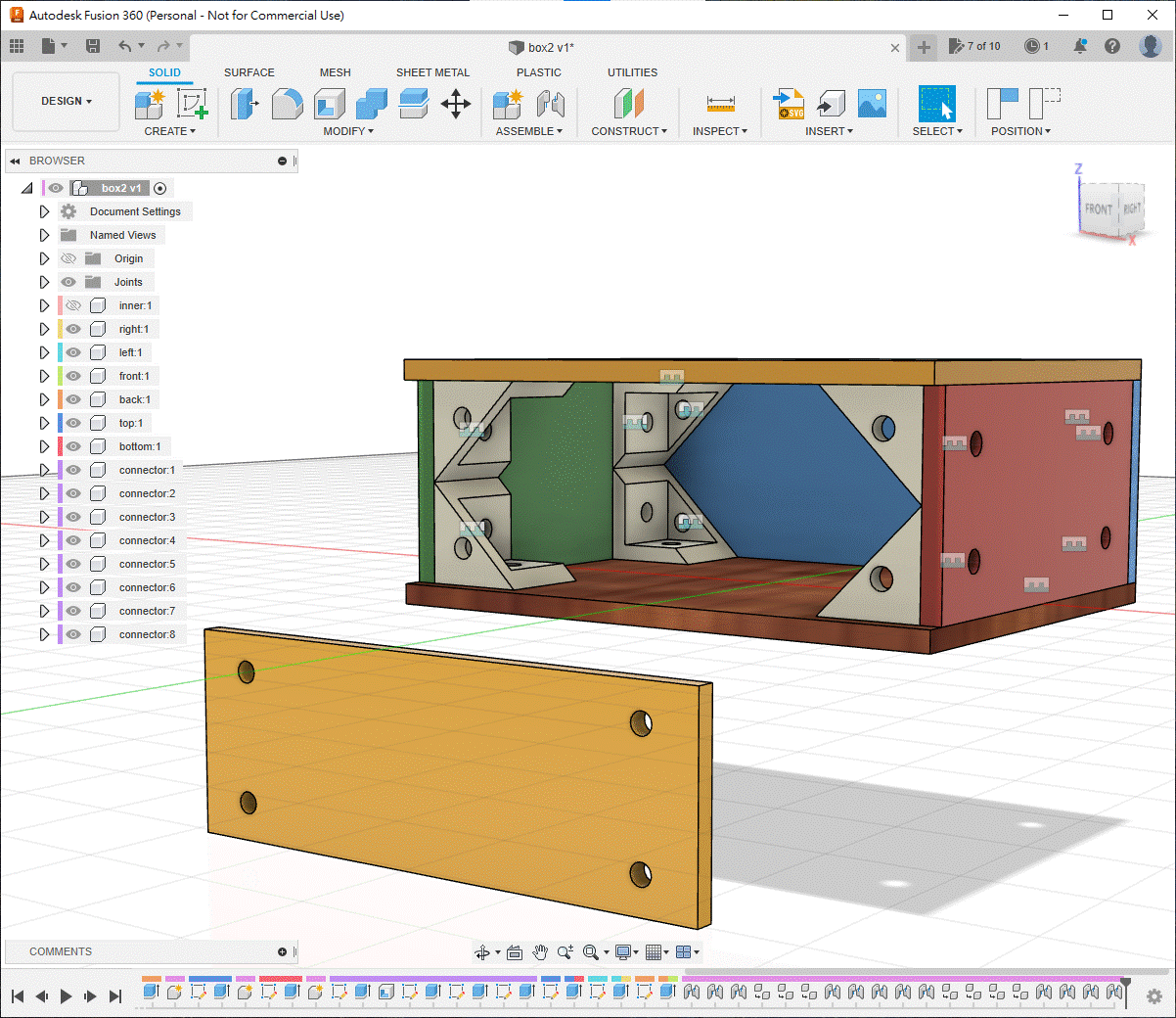
Finally, joint the front panel to any matching connector. Drag the finished box gently; if the whole assembly moves together, the joints are correct.
6. Resize the Box with Parameters
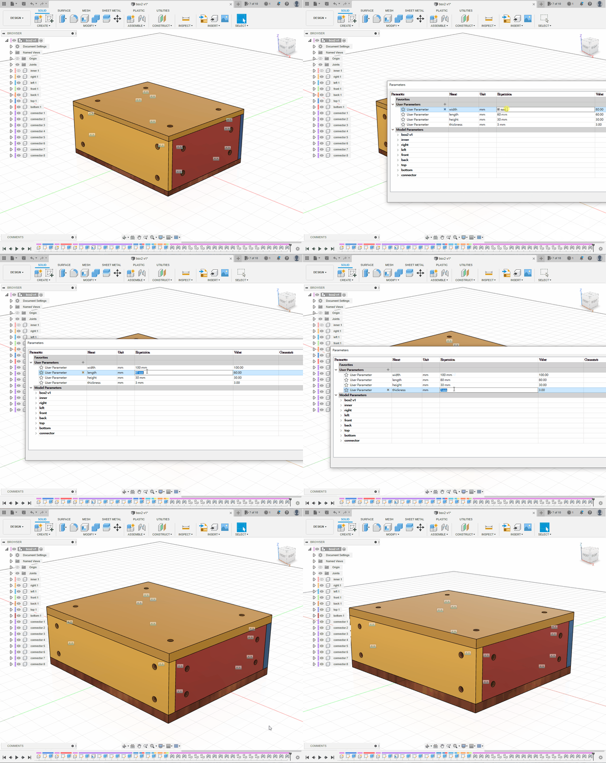
Change the box to width = 100 mm, length = 80 mm and thickness = 5 mm. Inspect the timeline for errors. If the complete model updates without warnings, it is ready to submit.
Translation notice: This English page was generated automatically by AI and has not yet been reviewed by a human. It will be checked and revised page by page when time permits.